
High clamping force · 15 – 10,000 Nm · reversing duty
JK3 Metal Bellows Coupling with Conical Clamping System
The JK3 uses the same stainless bellows as the JK2 but replaces the radial clamping screw with a conical clamping ring at each end. A ring is drawn axially against a matching cone on the hub by a circle of ISO 4017 bolts; as it advances it closes onto the shaft with a very high, evenly distributed surface pressure. The grip is uniform around the full circumference instead of being concentrated near a single screw.
That difference matters on two duties. The first is high torque: a conical ring converts bolt tension into radial pressure over the whole contact area, so the joint transmits far more torque than a slit hub of the same diameter. The second is reversing duty – presses, lifters and indexing tables that alternate direction under load – where any micro-slip at the hub eventually shows up as lost accuracy.
Integrated jacking threads make the coupling removable without a puller. Back the fastening bolts out, wind them into the jacking holes, and the conical ring is pushed off the cone; the coupling then slides off the shaft by hand. Nothing is hammered, and the shaft is not damaged during maintenance.
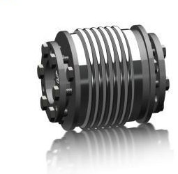
Product features
- Conical clamping ring at each end for maximum frictional grip
- Fastened with a circle of ISO 4017 bolts, tightened evenly
- Integrated jacking threads – dismounts without a puller or hammer
- High operational reliability under reversing and shock loads
- Bellows in high-grade stainless steel, hubs and conical rings in steel
- Short-term overloads up to 1.5 × TKN permissible
- Two standard overall lengths on most sizes
- Bores machined to order in H7, 10 to 180 mm depending on size
Design & materials
Bellows. High-grade stainless steel, concentrically mounted between the two hubs; carries the torque and all of the misalignment.
Conical clamping rings. Steel rings drawn onto a matching cone by ISO 4017 bolts. Bolt tightening torques are listed in the data table and must be applied evenly, in stages.
Jacking threads. Threaded holes in the hub accept the fastening bolts in reverse, pushing the ring off the cone at disassembly.
Bore. H7 as standard, 10-22 mm at size 15 up to 70-180 mm at size 10000. Bores may differ at the two ends.
JK3 bellows coupling: technical data
Sizes are nominal torque in Nm. Where a size lists several values, they correspond to the standard overall lengths offered for that size, in the same order.
Scroll the table sideways to see the larger sizes →
| Size | 15 | 30 | 60 | 150 | 200 | 300 | 500 | 800 | 1500 | 4000 | 6000 | 10000 |
|---|---|---|---|---|---|---|---|---|---|---|---|---|
| Nominal torqueNmTKN [Nm] | 15 | 30 | 60 | 150 | 200 | 300 | 500 | 800 | 1500 | 4000 | 6000 | 10000 |
| Overall lengthmmL [mm] | 48 55 | 57 65 | 66 76 | 75 87 | 78 90 | 89 103 | 97 110 | 114 | 141 | 195 | 210 | 217 |
| Bellows outside diametermmD [mm] | 49 | 55 | 66 | 81 | 90 | 110 | 124 | 133 | 157 | 200 | 253 | 303 |
| Hub fit lengthmmL1 [mm] | 19 | 22 | 27 | 32 | 32 | 41 | 41 | 50 | 61 | 80 | 85 | 92 |
| Bore diameter range, d1 (H7)mmd1 [mm] | 10–22 | 12–23 | 12–29 | 15–38 | 15–44 | 24–56 | 24–60 | 30–60 | 35–70 | 50–100 | 60–140 | 70–180 |
| Bore diameter range, d2 (H7)mmd2 [mm] | 10–22 | 12–23 | 12–29 | 15–38 | 15–44 | 24–56 | 24–60 | 30–60 | 35–70 | 50–100 | 60–140 | 70–180 |
| Hub outside diametermmD1 [mm] | 49 | 55 | 66 | 81 | 90 | 110 | 122 | 116 | 135 | 180 | 246 | 295 |
| Fastening bolt–Ms1 | 6xM4 | 6xM5 | 6xM5 | 6xM6 | 6xM6 | 6xM8 | 6xM8 | 6xM10 | 6xM12 | 6xM16 | 6xM16 | 8xM16 |
| Screw tightening torqueNmTA [Nm] | 4 | 6 | 8 | 12 | 14 | 18 | 25 | 40 | 70 | 120 | 150 | 160 |
| Moment of inertia10⁻³ kg·m²J | 0.07 0.08 | 0.15 0.16 | 0.39 0.41 | 1.2 1.6 | 1.7 2.5 | 5.1 5.9 | 9.1 9.9 | 13.2 | 34.9 | 85.5 | 254 | 629 |
| Approximate weightkgm [kg] | 0.26 | 0.5 | 0.9 | 1.3 | 1.8 | 3 | 4.3 | 5.7 | 8.3 | 23 | 32.7 | 45.6 |
| Torsional stiffness10³ Nm/radCT | 20 15 | 39 28 | 76 55 | 175 110 | 191 140 | 450 350 | 510 500 | 780 | 1304 | 3400 | 5700 | 10950 |
Show the full specification table (all 18 rows)
| Size | 15 | 30 | 60 | 150 | 200 | 300 | 500 | 800 | 1500 | 4000 | 6000 | 10000 |
|---|---|---|---|---|---|---|---|---|---|---|---|---|
| Nominal torqueNmTKN [Nm] | 15 | 30 | 60 | 150 | 200 | 300 | 500 | 800 | 1500 | 4000 | 6000 | 10000 |
| Overall lengthmmL [mm] | 48 55 | 57 65 | 66 76 | 75 87 | 78 90 | 89 103 | 97 110 | 114 | 141 | 195 | 210 | 217 |
| Bellows outside diametermmD [mm] | 49 | 55 | 66 | 81 | 90 | 110 | 124 | 133 | 157 | 200 | 253 | 303 |
| Hub fit lengthmmL1 [mm] | 19 | 22 | 27 | 32 | 32 | 41 | 41 | 50 | 61 | 80 | 85 | 92 |
| Bore diameter range, d1 (H7)mmd1 [mm] | 10–22 | 12–23 | 12–29 | 15–38 | 15–44 | 24–56 | 24–60 | 30–60 | 35–70 | 50–100 | 60–140 | 70–180 |
| Bore diameter range, d2 (H7)mmd2 [mm] | 10–22 | 12–23 | 12–29 | 15–38 | 15–44 | 24–56 | 24–60 | 30–60 | 35–70 | 50–100 | 60–140 | 70–180 |
| Hub outside diametermmD1 [mm] | 49 | 55 | 66 | 81 | 90 | 110 | 122 | 116 | 135 | 180 | 246 | 295 |
| Fastening bolt–Ms1 | 6xM4 | 6xM5 | 6xM5 | 6xM6 | 6xM6 | 6xM8 | 6xM8 | 6xM10 | 6xM12 | 6xM16 | 6xM16 | 8xM16 |
| Screw tightening torqueNmTA [Nm] | 4 | 6 | 8 | 12 | 14 | 18 | 25 | 40 | 70 | 120 | 150 | 160 |
| Jack screw for dismounting–Ms2 | 3xM4 | 3xM4 | 3xM5 | 3xM5 | 3xM6 | 3xM6 | 3xM6 | 3xM8 | 6xM8 | 6xM10 | 6xM10 | 8xM10 |
| Moment of inertia10⁻³ kg·m²J | 0.07 0.08 | 0.15 0.16 | 0.39 0.41 | 1.2 1.6 | 1.7 2.5 | 5.1 5.9 | 9.1 9.9 | 13.2 | 34.9 | 85.5 | 254 | 629 |
| Approximate weightkgm [kg] | 0.26 | 0.5 | 0.9 | 1.3 | 1.8 | 3 | 4.3 | 5.7 | 8.3 | 23 | 32.7 | 45.6 |
| Torsional stiffness10³ Nm/radCT | 20 15 | 39 28 | 76 55 | 175 110 | 191 140 | 450 350 | 510 500 | 780 | 1304 | 3400 | 5700 | 10950 |
| Max. axial misalignment± mmΔKa [±mm] | 1 2 | 1 2 | 1.5 2 | 2 3 | 2 3 | 2.5 3.5 | 2.5 3.5 | 3.5 | 3.5 | 3.5 | 3 | 3 |
| Max. lateral misalignment± mmΔKr [±mm] | 0.15 0.2 | 0.2 0.25 | 0.2 0.25 | 0.2 0.25 | 0.25 0.3 | 0.25 0.3 | 0.3 0.35 | 0.35 | 0.35 | 0.4 | 0.4 | 0.4 |
| Max. angular misalignment± °ΔKw [±°] | 1 1.5 | 1 1.5 | 1 1.5 | 1 1.5 | 1 1.5 | 1 1.5 | 1 1.5 | 1.5 | 1.5 | 1.5 | 1.5 | 1.5 |
| Axial spring rateN/mmCa [N/mm] | 25 15 | 50 30 | 72 48 | 82 52 | 90 60 | 105 71 | 70 48 | 100 | 320 | 565 | 1030 | 985 |
| Lateral spring rateN/mmCr [N/mm] | 475 137 | 900 270 | 1200 420 | 1500 435 | 2040 610 | 3750 1050 | 2500 840 | 2000 | 3600 | 6070 | 19200 | 21800 |
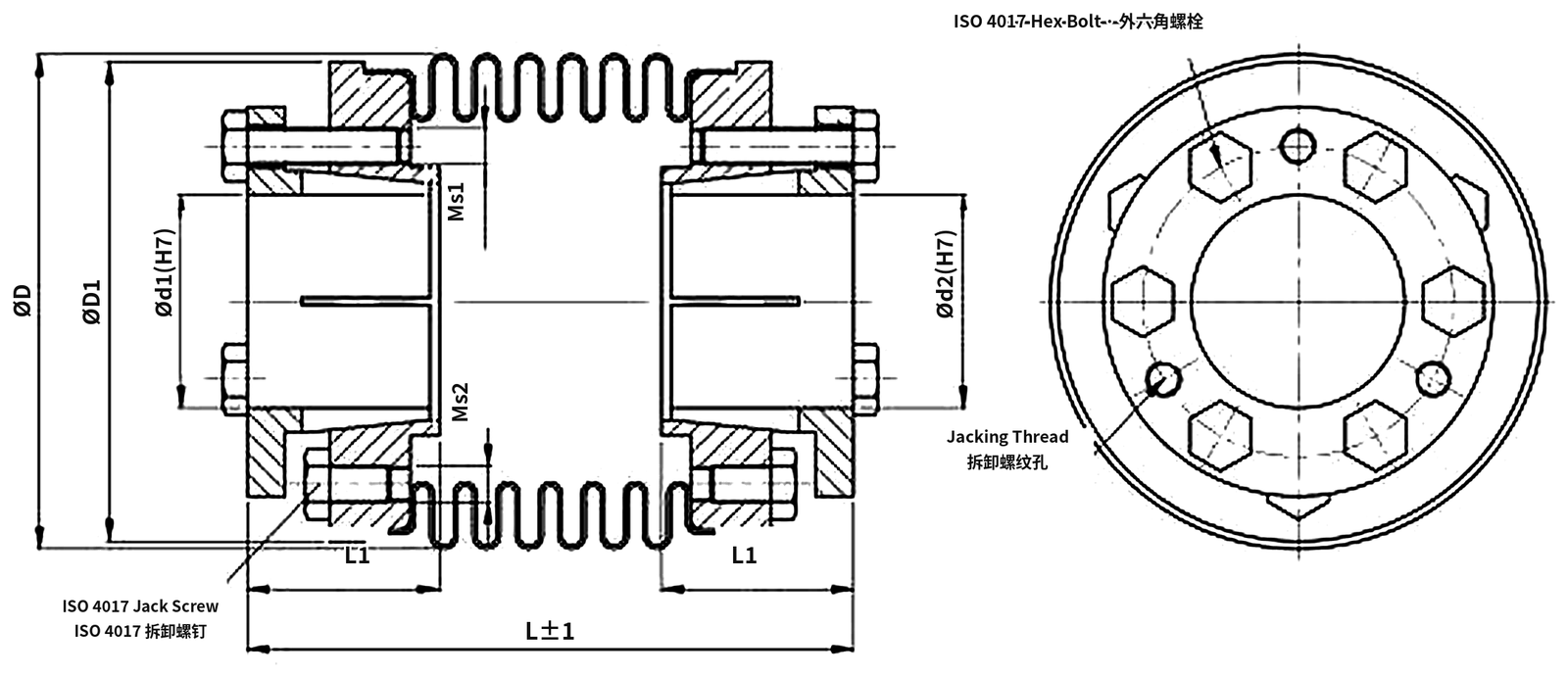
Dimensions
Made to your drawing
- Bores outside the standard table, different at each end
- Keyways to DIN 6885 where the duty requires a positive connection
- Reduced hub diameter for tight housings
- Special overall length
- Stainless hubs and rings for corrosive atmospheres
- Balanced assemblies for high-speed operation
Typical applications
Heavy-duty servo axes
Where torque is too high for a radial clamping hub.
Presses and forming machines
Reversing load with shock peaks.
Lifters and indexing tables
Frequent direction changes under load.
Gearbox input shafts
Conical rings adapt to a range of shaft diameters.
Machine tools
Rigid connection with no keyway to develop play.
Test and dynamometer rigs
Repeatable mounting and easy removal.
Frequently asked questions
How is the JK3 different from the JK2?
Both use the same stainless bellows. The JK2 clamps with one or two radial screws per hub; the JK3 clamps with a conical ring drawn up by a circle of bolts. The JK3 gives a much higher, more uniform grip and is the better choice for high torque and reversing duty, at the cost of a longer hub and a more involved installation.
Can the JK3 be removed without damaging the shaft?
Yes. The fastening bolts are wound into the integrated jacking threads, which push the conical ring off its cone. The coupling then comes off by hand – no puller, no hammer, no heat.
Do the bolts have to be tightened in a particular order?
Yes – evenly and in stages, like a cylinder head, to seat the ring parallel to the cone. The tightening torque for each size is in the data table; under-tightening loses grip, over-tightening strips the thread.
Is a keyway available?
Yes, to DIN 6885 on request. Without a keyway the joint is purely frictional, which is normally preferred because it removes the backlash that a keyway inevitably introduces.
Tell us the torque and the shaft
Send the duty torque, the shaft diameters and the available axial space; we will confirm the JK3 size and the bolt tightening data.