
Zero backlash · 15 – 10,000 Nm · bore 8 – 180 mm
JK2 Metal Bellows Coupling with Clamping Hub
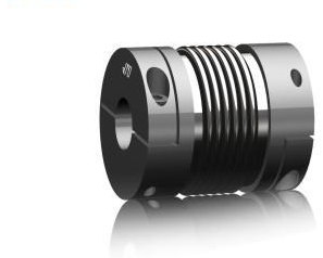
The JK2 metal bellows coupling is the standard MISHKIN design: two radial clamping hubs joined by a formed stainless steel bellows. Each hub grips its shaft with a single clamping screw (two screws from size 800 upwards) that closes a slit in the hub, so the coupling mounts without a key, without a taper bush and without any axial pre-load on the motor or gearbox bearing.
The clamping hub is a plain cylindrical fit, so the JK2 metal bellows coupling mounts on any shaft with an H7 bore and a smooth surface – no keyway has to be cut, and the coupling can be positioned anywhere along the shaft. That makes it the usual choice for servo motors, where the shaft is short, smooth and often already finished to h6.
The bellows is the only flexible element and the only part that moves. It bends to absorb axial, angular and lateral misalignment while staying torsionally rigid, which is what keeps a positioning axis free of lost motion. Short-term peak overloads of up to 1.5 × nominal torque are permissible, so a servo acceleration spike does not damage the coupling.
Product features
- Radial clamping screw installation – fast, and no keyway required
- Dual-bolt clamping system from size 800 upwards for higher clamping force
- Bellows in high-grade stainless steel, hubs in aluminium or steel
- Short-term overloads up to 1.5 × TKN permissible
- Several standard overall lengths per size, so the axial gap can be matched to the machine instead of the machine to the coupling
- Low moment of inertia, suited to high-dynamic servo drives
- Optional keyway to DIN 6885 on request
- Bores machined to order in H7, up to 180 mm on the largest size
Design & materials
Bellows. High-grade stainless steel, formed into convolutions and joined to the hubs concentrically. It carries the torque and provides all of the flexibility.
Hubs. Aluminium or steel depending on size – see the material row in the data table. Sizes 15 to 500 are supplied in aluminium or steel, from size 800 the hubs are steel.
Clamping. One radial screw per hub up to size 500, two screws from size 800. Tightening torques are listed in the table; exceeding them damages the screw thread, not the shaft.
Bore. H7 fit, keyway optional to DIN 6885. Any bore within the stated range can be supplied, including different bores at each end.
JK2 metal bellows coupling: technical data
The table covers the complete JK2 metal bellows coupling range. TKN is the nominal torque used to size the coupling; the remaining rows are dimensions and the values needed to check the shaft.
Sizes are nominal torque in Nm. Where a size lists several values, they correspond to the standard overall lengths offered for that size, in the same order.
Scroll the table sideways to see the larger sizes →
| Size | 15 | 30 | 60 | 80 | 150 | 200 | 300 | 500 | 800 | 1500 | 4000 | 6000 | 10000 |
|---|---|---|---|---|---|---|---|---|---|---|---|---|---|
| Nominal torqueNmTKN [Nm] | 15 | 30 | 60 | 80 | 150 | 200 | 300 | 500 | 800 | 1500 | 4000 | 6000 | 10000 |
| Overall lengthmmL [mm] | 59 66 99 | 69 77 113 | 83 93 130 | 94 106 143 | 95 107 144 | 105 117 163 | 111 125 200 | 133 146 169 | 140 179 | 166 230 | 225 | 252 | 288 |
| Bellows outside diametermmD [mm] | 49 | 55 | 66 | 81 | 81 | 90 | 110 | 124 | 134 | 157 | 200 | 253 | 303 |
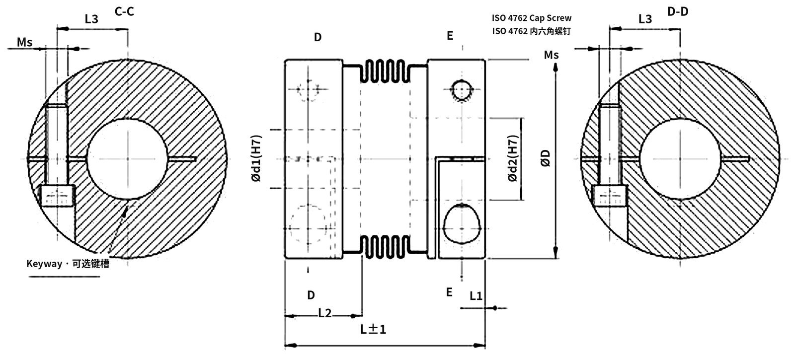
| Hub fit lengthmmL2 [mm] | 22 | 27 | 31 | 36 | 36 | 41 | 43 | 51 | 45 | 55 | 85 | 107 | 129 |
| Bore diameter range, d1 (H7)mmd1 [mm] | 8–28 | 10–30 | 12–35 | 14–42 | 19–42 | 22–45 | 24–60 | 35–60 | 40–75 | 50–80 | 50–90 | 60–140 | 70–180 |
| Bore diameter range, d2 (H7)mmd2 [mm] | 8–28 | 10–30 | 12–35 | 14–42 | 19–42 | 22–45 | 24–60 | 35–60 | 40–75 | 50–80 | 50–90 | 60–140 | 70–180 |
| Clamping screw–Ms | M5 | M6 | M8 | M10 | M10 | M12 | M12 | M16 | 2xM16 | 2xM20 | 2xM24 | 2xM24 | 2xM30 |
| Screw tightening torqueNmTA [Nm] | 8 | 15 | 40 | 50 | 70 | 120 | 130 | 200 | 250 | 470 | 1200 | 1200 | 2400 |
| Moment of inertia10⁻³ kg·m²J | 0.06 0.07 0.08 | 0.12 0.13 0.14 | 0.32 0.35 0.4 | 0.8 0.85 0.9 | 1.9 2 2.1 | 3.2 3.4 3.6 | 7.6 7.9 8.3 | 14.3 14.6 14.8 | 16.2 17 | 43 45 | 165 | 495 | 1214 |
| Approximate weightkgm [kg] | 0.18 | 0.28 | 0.49 | 0.8 | 1.86 | 2.66 | 4 | 5.8 | 6.4 | 11.6 | 28.8 | 49.5 | 81 |
| Torsional stiffness10³ Nm/radCT | 20 15 14 | 39 28 27 | 76 55 54 | 129 85 84 | 175 110 97 | 191 140 135 | 450 350 340 | 510 500 400 | 780 711 | 1304 1180 | 3400 | 5700 | 10950 |
Show the full specification table (all 19 rows)
| Size | 15 | 30 | 60 | 80 | 150 | 200 | 300 | 500 | 800 | 1500 | 4000 | 6000 | 10000 |
|---|---|---|---|---|---|---|---|---|---|---|---|---|---|
| Nominal torqueNmTKN [Nm] | 15 | 30 | 60 | 80 | 150 | 200 | 300 | 500 | 800 | 1500 | 4000 | 6000 | 10000 |
| Overall lengthmmL [mm] | 59 66 99 | 69 77 113 | 83 93 130 | 94 106 143 | 95 107 144 | 105 117 163 | 111 125 200 | 133 146 169 | 140 179 | 166 230 | 225 | 252 | 288 |
| Bellows outside diametermmD [mm] | 49 | 55 | 66 | 81 | 81 | 90 | 110 | 124 | 134 | 157 | 200 | 253 | 303 |
| Hub fit lengthmmL2 [mm] | 22 | 27 | 31 | 36 | 36 | 41 | 43 | 51 | 45 | 55 | 85 | 107 | 129 |
| Bore diameter range, d1 (H7)mmd1 [mm] | 8–28 | 10–30 | 12–35 | 14–42 | 19–42 | 22–45 | 24–60 | 35–60 | 40–75 | 50–80 | 50–90 | 60–140 | 70–180 |
| Bore diameter range, d2 (H7)mmd2 [mm] | 8–28 | 10–30 | 12–35 | 14–42 | 19–42 | 22–45 | 24–60 | 35–60 | 40–75 | 50–80 | 50–90 | 60–140 | 70–180 |
| Clamping screw–Ms | M5 | M6 | M8 | M10 | M10 | M12 | M12 | M16 | 2xM16 | 2xM20 | 2xM24 | 2xM24 | 2xM30 |
| Screw tightening torqueNmTA [Nm] | 8 | 15 | 40 | 50 | 70 | 120 | 130 | 200 | 250 | 470 | 1200 | 1200 | 2400 |
| Clamping screw offsetmmL3 [mm] | 17 | 19 | 23 | 27 | 27 | 31 | 39 | 41 | 2×48 | 2×55 | 2×65 | 2×90 | 2×117 |
| Screw edge distancemmL1 [mm] | 6.5 | 7.5 | 9.5 | 11 | 11 | 12.5 | 13 | 16.5 | 18 | 22.5 | 28 | 35 | 42 |
| Moment of inertia10⁻³ kg·m²J | 0.06 0.07 0.08 | 0.12 0.13 0.14 | 0.32 0.35 0.4 | 0.8 0.85 0.9 | 1.9 2 2.1 | 3.2 3.4 3.6 | 7.6 7.9 8.3 | 14.3 14.6 14.8 | 16.2 17 | 43 45 | 165 | 495 | 1214 |
| Hub material (std. / opt.)– | Al/St | Al/St | Al/St | Al/St | St/Al | St/Al | St/Al | St/Al | Steel | Steel | Steel | Steel | Steel |
| Approximate weightkgm [kg] | 0.18 | 0.28 | 0.49 | 0.8 | 1.86 | 2.66 | 4 | 5.8 | 6.4 | 11.6 | 28.8 | 49.5 | 81 |
| Torsional stiffness10³ Nm/radCT | 20 15 14 | 39 28 27 | 76 55 54 | 129 85 84 | 175 110 97 | 191 140 135 | 450 350 340 | 510 500 400 | 780 711 | 1304 1180 | 3400 | 5700 | 10950 |
| Max. axial misalignment± mmΔKa [±mm] | 1 2 3 | 1 2 3 | 1.5 2 3 | 2 3 4 | 2 3 4 | 2 3 4 | 2.5 3.5 4.5 | 2.5 3.5 4.5 | 3.5 4.5 | 3.5 4.5 | 3.5 | 3 | 3 |
| Max. lateral misalignment± mmΔKr [±mm] | 0.15 0.2 1 | 0.2 0.25 1 | 0.2 0.25 1 | 0.2 0.25 1 | 0.2 0.25 1 | 0.25 0.3 1 | 0.25 0.3 1 | 0.3 0.35 1 | 0.35 1 | 0.35 1 | 0.4 | 0.4 | 0.4 |
| Max. angular misalignment± °ΔKw [±°] | 1 1.5 2 | 1 1.5 2 | 1 1.5 2 | 1 1.5 2 | 1 1.5 2 | 1 1.5 2 | 1 1.5 2 | 1 1.5 2 | 1.5 2 | 1.5 2 | 1.5 | 1.5 | 1.5 |
| Axial spring rateN/mmCa [N/mm] | 25 15 84 | 50 30 118 | 72 48 165 | 48 32 144 | 82 52 130 | 90 60 280 | 105 71 605 | 70 48 85 | 100 285 | 320 440 | 565 | 1030 | 985 |
| Lateral spring rateN/mmCr [N/mm] | 475 137 140 | 900 270 224 | 1200 420 337 | 920 290 401 | 1500 435 500 | 2040 610 750 | 3750 1050 1200 | 2500 840 614 | 2000 1490 | 3600 1700 | 6070 | 19200 | 21800 |
Dimensions
Made to your drawing
- Bores other than the standard range, with different diameters at each end
- Keyways to DIN 6885, or a bore with no keyway at all
- Hub outside diameter reduced to clear a housing
- Stainless or coated hubs for wet or washdown areas
- Special overall length between the two hub faces
- Balanced assemblies for high-speed spindles
Typical applications
Servo drives
Motor to ball screw or gearbox input, where backlash would show up directly as positioning error.
CNC machine tools
Axis drives, tool changers and spindle drives.
Linear actuators and gantries
Short axial space between motor and screw.
Packaging machinery
High cycle rates with frequent reversal.
Test benches
Low inertia and known torsional stiffness for measurement.
Printing and paper handling
Register accuracy at speed.
Frequently asked questions
What is the maximum speed of a JK2 bellows coupling?
The datasheet does not state a single speed limit because it depends on size, overall length and balance quality. Tell us the speed and the bore and we will confirm the execution, and balance the assembly if required.
How much misalignment can the JK2 accept?
It depends on the size and on which of the standard lengths is used. For size 30 the permissible values are 1-2 mm axial, 0.2-0.25 mm lateral and 1-1.5° angular; the exact figures for every size are in the data table on this page and in the JK2 datasheet.
Can I get a keyway on the JK2?
Yes. A keyway to DIN 6885 can be machined on request. In most servo applications it is not needed – the friction of the clamping hub transmits more torque than the shaft can carry.
What bore tolerance do you machine to?
H7 as standard. If your shaft is finished to another tolerance, tell us the actual shaft diameter and we will match the bore to it.
Send us your shaft drawing
Bore, keyway, torque, speed and the axial gap between the shafts is all we need to select and quote the JK2 metal bellows coupling.